Quick links!HOME Items for SALE Price Guide Links CONTACT US !OUR Policy's
|
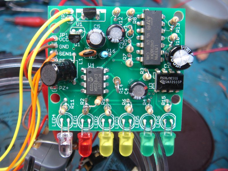
This is the board with the wires already attached. Yellow wires: These go to a switch that turn the alarm kit on and off. Red and Brown wires: These are the power wires. I used a rechargable battery, and installed charger port. Two orange wires: These go to a switch and speaker. I can use the detector as an EMF detector or vibration detection. No one walks by this without you knowing. |
 |
|
|
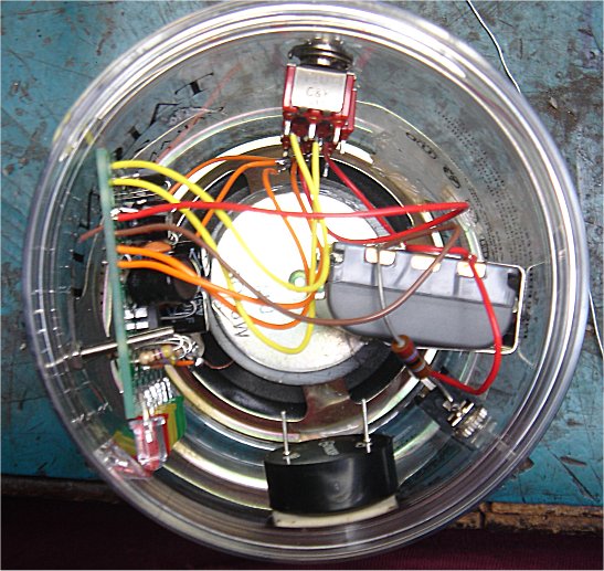
The speaker went in first. Ideal speaker for this is a 3-4 inch. Notice the battery and battery clip (large plastic grey part). This was made for a camcorder. I bought the battery at Radio Shack on clearance for $1.98 I get about 48 hours from this battery. Directly below the battery you can see the charging port with the current limit resistor going to it from the battery. Just below the charging port you see a black cylinder with two wire coming out of it. This is the peizo buzzer connected across the resitor (R14). This is the audible part of the alarm. |
|
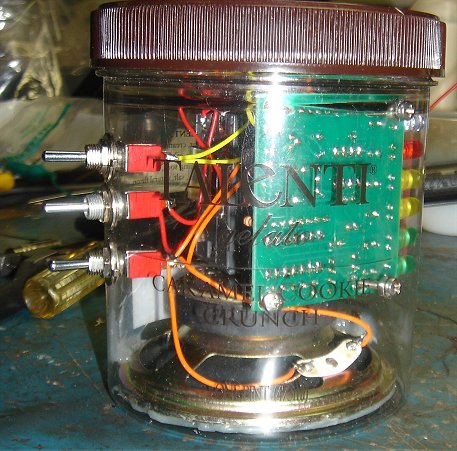
Notice the Piezo again: This just needs a small hole to be effective. I used double sided tape to hold it in place. If you listen close enough, you can hear the alarm going right now! You can see how I mounted the circuit board so the LED can be easily
seen from the outside. |
 |
|
|
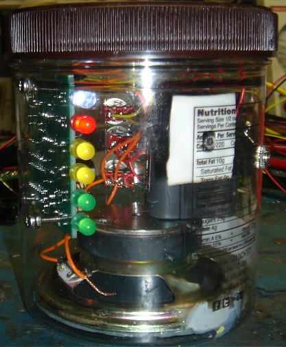
You can see the circuit board and how it is mounted with very small screws. The three switches are as follows from top to bottom: 1) Alarm active/deactivated. 2) power on/off. 3) EMF, Vibration sense. Also notice the cover has been screwwed back in place completing the system. |
Quick links!HOME Items for SALE Price Guide Links CONTACT US !OUR Policy's